Stefan Schaefer DK7FC raised a 200m vertical wire antenna to about 70 or 80 degrees elevation using a 8.1m^2 power kite, in less than ideal conditions. The transmitter delivered about 500 Watts at 0.9A into the loading coil to develop about 20kV on the antenna wire.
Here is Stefan's description of an epic solo transmission effort:
I arrived at about 9:40 UTC. It was no problem to arrange the equipment and nothing was forgotten. Just before, the rain stopped but the wind was a little to weak. I used the 8,1m^2 kite but it took some hours until the wind was enough, sadly. First, the wind increased just for some minutes. In that time i saw that the wire was to long and was sagging to much.
After cutting some meters i could start the generator and PA and turned the VFO wheel down until i saw a peak on the amperemeter. It was on 5,7 kHz but it was due to a very low kite angle. Later, as the wind increased i could do more useful resonating tests. I found that i can resonate between about 6,4 kHz to 6,6 kHz. Maybe this is due to the fact that the wire has to be slighty longer than 200m since the kite braid is elastic and will be 20m (10%) longer at strong wind. After watching the 6,5 kHz sector in the last weeks i found that it is best to transmit not on n*50 Hz or n*16,6667 Hz (frequency of the german trains grid). Thus i decided to go about into the center, to 6470,00 Hz, within the 46 km band! :-) First it was not possible to transmit a real "message" since the wind was OFF sometimes :-(. My plan was to transmit "CU" in DFCW-600.
Than, an accident happened: Suddenly the [wind] was off and i wasn't fast enough to bring the kite down on the road. So the 200 Euro kite dropped in a 15m high tree! I felt like a child that lost his parents on the airport! I was not strong enough to pull it out there with its braid. I saw no other way to try it with the car, even when the kite gets damaged with this attempt. So i fastened the braid on the car and drove some 10m until there was a heavy pull on it. The braid stopped in a beginning corner of a corn field and as i lifted it above the corn it sounded like a lash/whip. But suddenly the kite came out of the tree and before it dropped on the bottom it was caught by the wind and rised into the sky, hanging on my car :-) I drove back the the TX coil with the kite on the car...
After taking too much sun and after this stress i was powerless and not motivated to improve the earth losses and so on but it was my absolute goal to produce some nice signals for the RX stations, at least a limple carrier! So i set up the whole arrangement and now the wind was stable, lifting the kite continously above 45 deg, sometimes 70 deg. In proper wind conditions, it is lifted to 70...80 deg. The antenna current was about 750mA and after connecting the copper rod i hammered into the soil in the 5th experiment it rised to 800mA. Then i reduced the primary winding number from 70 to 60. Then, the current was up to 920 mA, the highest current so far. Just before 16 UTC the fuel of the generator was empty and my fuel as well ;-) That was the end of the 6th experiment.
The transmission was visible on several receiver spectrograms, the furthest being that of Michel Brunel F5WK at 460km. Wolf Buescher DL4YHF obtained the clearest reception, at a range of 264km, shown here.
Reception at Todmorden, UK (53.703N 2.072W, range 859km) was difficult due to the
high background noise level, averaging around 95fT/(root Hz) on the bearing
of the transmitter. This is
about 3 times the winter noise level.
Fortunately for reception in Todmorden, the transmission was mostly unmodulated,
which allowed long period integration to detect the signal.
With careful choice of
noise blanker settings it was possible to extract the signal
from a 12 minute transmission of continuous
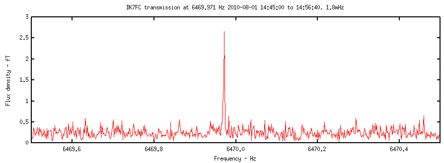
carrier. The optimum bandwidth was found to be 1.8mHz, revealing
the signal at 6469.971Hz to be approximately 2.5fT (+/-50%) amplitude.
The peak is above 10 sigma, as shown below.

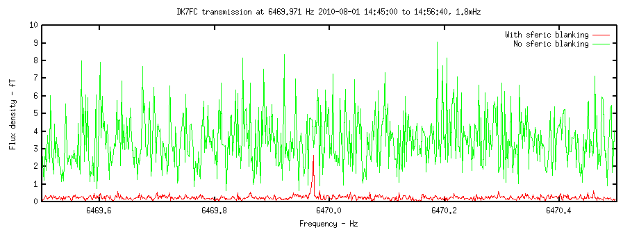
The optimum noise blanking threshold was found to be equal to the mean amplitude, applied after pre-filtering the raw VLF signal to a bandwidth of 4kHz to 8kHz. This level of blanking produced a factor of 15 reduction in background noise level. For comparison, the graph below shows the same portion of signal analysed at the same settings, but without the noise blanking.

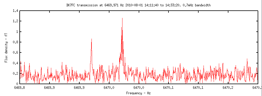
Trial and error was used to select the 1.8mHz bandwidth, which is consistent with the 12 minute transmission period. A 22 minute continuous carrier was broadcast a little earlier in the afternoon at a lower ERP. The optimum bandwidth for this transmission was found to be 0.7mHz, revealing the signal at 1.0fT, about 6 times the mean noise, in the following spectrum,

At this narrow bandwidth, there is some sign that the signal energy is being spread due to transmitter drift. It is also apparent that some frequency shift keying was in use during this transmission.
The large effect of noise blanking demonstrates that the VLF background at this frequency is dominated by sferic energy. After blanking, the remaining background is similar to the post-blanking level observed in winter. It is possible then that VLF reception of narrow band signals can be made equally well independently of season if suitable sferic blanking is applied.
The 2.5fT signal is weaker than might be expected from the estimated ERP, by about a factor of 2 or 3. It is possible that the marginal wind conditions at the transmitter prevented the estimated ERP from being obtained continuously. The precise times of the transmission were not recorded so it is likely that some loss of S/N ratio has occurred as a result. Also there is considerable margin for error in the receiver's amplitude calibration.
Todmorden receiver: Orthogonal loops 20m^2, sensitivity 1.5fT in 1Hz, 24 bit capture of 0-96kHz, samples timestamped to +/-100nS of UT.
Some previous amateur transmission tests at VLF: Summary of 9kHz tests.