| TSSP: Secondary Miscellanae |
Various Tesla secondary related topics.
Updated: 19 Jul 2008
As far as we know the first successful theoretical study of the behaviour
of a solenoid near to its lowest self resonance was published in 1921
by Breit[1]. Earlier attempts where either flawed or involved too much
approximation to claim any relevance to real coils. Breit used the
quasi-static field approximation to obtain a differential equation for
the current in the case of very small h/d. An expression for the internal
capacitance is obtained by treating the coil as a stack of conducting
rings each carrying a uniform charge. The use of an approximation to
the elliptic integral coefficients (which relate the potential induced at
a point on the coil to the source charge on each ring) allowed Breit to
derive an expression for the effective shunt capacitance in free space.
This is extended by Breit to include the external capacitance due to
an elliptical shield around the coil - the choice being made to allow
transformation of the description to the elliptic coordinates in which
the equations become tractable. The small h/d restriction enables Breit to
use the uniform EMF per turn approximation, ie a linear voltage gradient,
which allows an expression for the current profile to be obtained. Breit
mentions experimental work carried out at the Johns Hopkins University
and provides measured current profiles in support of his theoretical
predictions.
The differential equations for the solenoid employed in this project
are derived in essentially the same way as Breit, although with our
numerical computational approach we do not have to limit the analysis
to any particular h/d, voltage gradient, or configuration. As per Breit
we obtain the physical reactance distributions by means of elliptic
integrals over charge rings and current filament rings, and we form
a differential equation on the basis of the charge conservation and
magnetic induction laws.
We are pleased to note that we obtain the same current profiles as Breit,
in which the elevated current maximum is prominent.
A recurring myth concerns the idea that the length of wire wound into the secondary solenoid can be used to determine the resonant
frequency on the basis of its free space quarterwave length. That this is not the case is easily demonstrated by comparing the
measured resonant frequency with the 'wire quarter wave' frequency. The actual resonant frequency is always considerably higher, typically
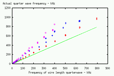
between 20% to 100% higher. The graph below compares the actual resonant frequency against the wire quarter-wave frequency for a sample of
around 200 simulated, unloaded, tesla secondaries - with their positions marked with dots.

The green line shows the line of equality. The red dots
are coils with h/d < 2, the blue crosses are coils with 2 < h/d < 6, and the purple squares are coils with h/d > 6.
It can be seen that the greatest discrepancy occurs with large h/d coils, which can resonate at up to twice the frequency predicted
on the basis of wire length.
In 1947 R.G. Medhurst [2] published a well known work in which empirical
results of self capacitance measurements were presented in the form of
tables. These results apply to single layer solenoids mounted horizontally
above a ground plane with one end earthed, at frequencies below the
self resonant frequency of the coil. They were obtained by resonating
test inductors with large external capacitances, and extrapolating the
results to the case of zero externally applied capacitance. As such
they are ideal for use in radio engineering applications, in which coils
are normally operated below their self resonant frequencies, and the
Medhurst self-capacitance is offered as an adjustment to the circuit
capacitance for use under these conditions. The Medhurst capacitance
Cmed is therefore valid only when the coil is carrying an approximately
uniform current at a frequency well below the lowest self resonance,
which is clearly not the case with Tesla coils. As a result, attempting to
apply the formula f = 1/(2 * PI * sqrt( Ldc * Cmed) is likely to introduce
some error when estimating the resonant frequency of a Tesla secondary.
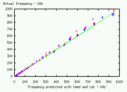
The graph below compares the actual resonant frequency of a sample of simulated unloaded secondaries, against the frequency
predicted on the basis of the Medhurst formula.

The green line indicates the line of equality and the simulated coils are
marked with purple squares for large h/d, blue crosses for medium h/d, and
red dots for small h/d. Although it does quite a good job with coils of
small h/d, the Medhurst capacitance on the whole tends to under-estimate
the resonant frequency, the error being up to 10% or more for large
h/d. The under-estimate also increases when the secondary is raised above
its working ground plane. The discrepancy arises mainly from the varying
utilisation of the inductance at the resonant frequency. Unloaded coils
of large h/d exhibit a very roughly cosinusoidal profile to their current
distribution, and thus the apparent inductance is less than that of the
same inductor fed with the same base current but at a lower frequency. At
small h/d, a substantial circulating current forms within the coil,
raising the location of the maximum current towards the middle of the
coil, and raising its magnitude anything up to 40% above that of the base
current. The result is an effective coil utilisation which can be greater
than the low frequency value. Typically the equivalent series inductance
at resonance can vary between 0.7 Ldc at large h/d and low elevation, to
1.1 Ldc at small h/d and high elevation. This variation of the effective
inductance accounts for much of the error in the 'Medhurst frequency',
since the original results were obtained with a coil charge distribution
and inductance utilisation appropriate to that of a uniform current.
Having pointed out the potential error in the use of Cmed, it has to
be said that once the coil builder has equiped the secondary with the
various adornments necessary to operate it, the extra capacitance thus
introduced helps to improve the apparent accuracy of Cmed. Furthermore,
use of a topload raises the coil utilisation on the larger h/d coils by
enforcing a more uniform current. For these reasons the use of Cmed for
practical design work is therefore often justifiable.
[1] G. Breit,
"Distributed Capacity of Inductive Coils",
Physical Review, Jun 1921, V17, Part 6, p649-677
[2] "HF Resistance and Self-Capacitance of Single-Layer Solenoids", R.G. Medhurst, Wireless Engineer, Feb and March 1947.
Maintainer Paul Nicholson, tssp1611@abelian.org.

