The direct turn-to-turn capacitance makes a small and usually
negligible contribution to the overall effective reactances
of typical primary and secondary coils. But a primary design
involving a wide compact spiral ribbon exhibits a particularly
large turn-to-turn capacitance, and the question is - can we
still ignore it when making design calculations?
Chris Swinson wrote:
> my primary will be 4 turns of 2" wide strap separated
> about 1mm apart.. the dia is about 22"
This particular coil is a good candidate for discussion, and
the topic is worth pursuing due to the evolving requirements
for lower impedance primary windings demanded by some of the
modern TC designs.
It turns out that the turn-to-turn capacitance here has a very
large effect on the self resonance of the coil compared with a
wire coil of the same dimensions and turns. When this primary
coil is resonated with a primary capacitor, the change in the
resonant frequency is much less, but could still be significant
in precision coil design and modelling.
The lowering of the resonant frequency due to this inter-turn
capacitance occurs by increasing the effective inductance of
the coil, an increase which comes about as a result of circulating
currents raised within the coil - currents which pass through the
inter-turn capacitance.
These notes describe in some detail just how this occurs, and
explains why it is the inductance that alters and not
the resonator's capacitance. A spice model of the coil is used
to demonstrate the modelling principles and to estimate the
effective parameters of this coil.
Some concepts will have to be
introduced which may not be familiar to coilers who have not
delved into the finer details of modelling distributed resonators,
and it is hoped these notes will make an interesting introduction
to the subject.
It is necessary to distinguish between two types of self capacitance
which occur in a coil. The term 'self capacitance' is often
used casually in discussions, but here we need to be a little more
precise and recognise the difference between the
internal and external capacitance of the coil.
The external capacitance is the one which tends to be visualised
by coilers. It involves lines of the E-field leaving
the coil and terminating somewhere in the surroundings.
By contrast, the internal
capacitance accounts for E-field flux lines which leave one part
of the coil and terminate on another.
The important
distinction between internal and external - and the reason we do
in fact bother to separate them - is that only current
passing through the external capacitance (plus any load current)
eventually returns back to the source. The total current through external
capacitance (plus the load current) equals the base or drive current.
Note, we are picturing coils here with one end grounded and the
other, the 'hot' end, either open, or loaded by a tank or toroid
capacitance. Later we will model some coils and for modelling
purposes we will excite the resonator with a current source
inserted between the 'cold' end of the coil and ground. This
current source, therefore, carries the total current through the
external capacitance of the coil and load.
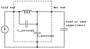
In contrast, current passing through the internal capacitance of
the coil does not leave the coil, and is invisible to the external
circuit and our current source. It makes itself felt, as we shall
see, by modifying the effective inductance of the coil at frequencies
where significant current passes through the internal capacitance.

| A lumped circuit which helps to visualise the two types of self capacitance. The current source feeds current into the coil, which eventually returns via either the external self capacitance or via the load/tank capacitor. Current through the internal capacitance is not accessible to the external circuit. |
In most coils (secondary and primary), the internal capacitance does
not affect the coil parameters very much. For example, in a typical
secondary coil, the effective inductance at the operating frequency
might be increased by 5 to 10% due to internal capacitance.
The contribution of internal capacitance does become dominant at
the higher (overtone) resonances of the coil (in which an in-coil wavelength
spans only a few turns), and also in very short (h/d < 1) coils and
coils with multiple layers.
The direct capacitance between consecutive turns can be quite high in a typical primary or secondary coil, with values ranging from 20pF to 200pF per turn. However, the contribution of this turn-to-turn capacitance to the overall effective reactance of the coil turns out to be quite small for typical solenoid and spiral coils.

| The palermo formula calculates the turn-to-turn capacitance of a pair of turns of diameter D. Epsilon is the absolute permittivity of whatever material fills the space between the conductors. It applies only to wire conductors of round cross section. |
This limited effect occurs because the inter-turn voltage is
generaly only a small fraction
(about 1/N in an N turn coil),
of the total coil voltage.
Turns further apart also
have a mutual capacitance between them, which is much lower of course,
but the voltage between each pair of these 'remote' turns is higher,
and there are about N-squared/2 pairs of these mutual capacitances
all contributing to the internal capacitance.
In the end, the remote turns dominate in the coils we normally use
and as a result, the internal capacitance tends to be governed by the overall
geometry of the coil, rather than the direct inter-winding capacitance.
The turn-to-turn capacitance contributes about 10% to the total internal
capacitance, but this internal capacitance itself
affects the resonant frequency only about 5%. We usually then neglect
the inter-turn capacitance when constructing models of the coil's
reactances.
The above reasoning applies to 'normal' coils which we have
frequently measured and modelled to confirm these statements.
A coil made of parallel ribbon is likely to have a rather larger
turn-to-turn capacitance.
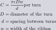
| Formula for the turn-to-turn capacitance between turns of a spiral ribbon coil. This is just the formula for the capacitance between parallel plates having the area of a turn - the circumference times the ribbon width. |
This parallel plate formula will be applied now when we set up an approximate model of the coil's internal capacitance.
Both the internal and external capacitances, as well as the
coil's inductance, are distributed along
the coil and cannot be directly represented in a circuit diagram.
We have to approximate these distributed reactances by segmenting
the resonator into a number of pieces and lumping the inductance
and capacitance of each segment. This involves an approximation,
of course, but we can achieve whatever accuracy we desire by
choosing to segment the resonator into larger numbers of smaller
pieces.
A distributed resonator usually has many resonant frequencies,
the collection of which is sometimes called the mode spectrum.
The lumped equivalent circuit can only represent a certain number
of these modes, that number increasing as the segmentation of the
model is made finer. The worst case is segmentation into just one
piece, as in the diagram above. This single LC model can only
represent one resonant mode, which is often adequate. But the
actual values of the lumped inductance and capacitance to be used
in that
single LC circuit have to be derived from a model which uses a finer
segmentation if the model is to accurately represent operation at
the single resonant mode.
For easy visualisation, we will segment this four-turn coil into
four segments, ie one segment per turn.
For the coil under discussion, its 56cm diameter and 1mm spacing
produce turn-to-turn capacitance of about 780pF. Added to this
are the longer range contributions, of which there are
N * (N-1)/2 - N + 1 pairs of mutual capacitances
in an N turn coil. For this coil, that's only 3 more!
We can even itemise them!
Only the edges of
the ribbon act as electrodes for the longer range internal
capacitances, so we can model these terms
as if they were thin wires and use a capacitance extraction program
to determine their values for each pair of turns.
 Pair 1:  2 turns gap  4.8pF
 Pair 2:  3 turns gap  4.7pF
 Pair 3:  2 turns gap  4.8pF
The three inter-turn capacitances of 780pF plus the three longer range internal capacitances listed above might be represented in a circuit model thus:-
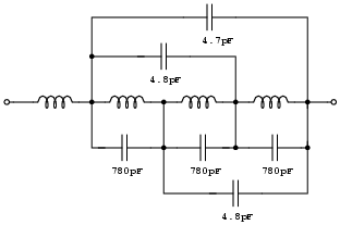
| This is just one way to approximate the distributed internal capacitances in a lumpy turn-by-turn model. There is some leeway over just where you choose to hang the capacitances. |
It seems likely that in this extreme coil we cannot off-hand disregard the turn-to-turn capacitance as we do in a more typical coil. In fact, the inter-turn capacitance dominates the internal capacitance of this coil.
To complete this simple four-segment model we have to add on the external
capacitances - that is, the distributed capacitance between each
segment
of the coil and the grounded surroundings.
Some further capacitance extraction gives some external capacitance samples
which are added here to the model.
|
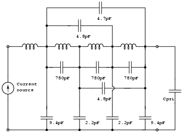
The network model with external capacitance added. These values are only
qualitative and the external capacitance in reality would vary somewhat
with the coil's relationship to its surroundings.
The two 'inside' turns are only contributing 2.2pF each. The exposed surfaces of the inner and outer turns add a little more. The 'load' in this case is the primary tank Cpri attached to the 'hot' end of the coil on the right, and imagine a drive source applied to the left hand terminals. |
This network model is not quite in a fit state to present to a circuit simulation program, we need to do a little more work to establish a value for the four inductances shown in the diagram, which are the self inductances of each turn. Also, not shown in this diagram, are the mutual inductances between each turn, which are very important. Later we will describe how these are constructed, but for now we will continue to discuss the capacitances.
Apply a constant DC voltage to the input terminals. All the
internal capacitances are shorted by coils, and all the external capacitances
and Cpri are charged up to the source voltage.
In this statically charged condition, the total stored charge is equivalent
to that of a single capacitance equal to
the parallel combination of all the external and load capacitances -
in this case 23.2pF + Cpri. This we define
as the Cdc of the resonator,
and the Cdc due to the coil alone is 23.2pF.
This quantity can be measured directly simply by connecing a capacitance meter
to the coil - so long as the operating frequency of the meter is
much lower than the lowest resonant frequency of the coil. This direct
measurement of Cdc can be a
useful cross check on the extracted values of the external capacitance.
Imagine now an AC drive signal set to the lowest resonance of the
network - the fundamental. In this mode of resonance,
all the circuit voltages
are in phase - meaning - they all waggle up and down in unison.
Also, assume that the induced voltage across each turn is
the same, or in other words, a linear voltage rise exists along the winding.
This will be the case, approximately, because of the mutual coupling
between the compact turns, as will be seen later.
Let this voltage per turn be Vt and picture
the circuit 'frozen' at an instant in the AC cycle in which
all the coil currents are momentarily zero while at the same
time, Vt is at a peak of its sinusoid. At this point in the
oscillation, all the stored energy is held in the E-field of the coil.
Let us list all the stored charges in the system, on the basis
of Q = CV for each of the 11 capacitances.
4.7 * 3Vt * 1 cap (int) 4.8 * 2Vt * 2 caps (int) 780.0 * 1Vt * 3 caps (int) 9.4 * 1Vt * 1 cap (ext) 2.2 * 2Vt * 1 cap (ext) 2.2 * 3Vt * 1 cap (ext) 9.4 * 4Vt * 1 cap (ext) Cpri * 4Vt * 1 cap (Cpri) | The charges are given in units of pico-Coulombs. Each contribution is weighted by the voltage across the capacitance, ie Q = CV. |
It is important to remember now that only the external capacitances and Cpri have their charge displacements supplied directly from the drive loop. The total charge supplied by our current source to set up this linear voltage distribution is therefore the sum of all the external and Cpri charges, ie
Vt * (9.4 * 1 + 2.2 * 2 + 2.2 * 3 + 9.4 * 4 + Cpri * 4)
which comes out to Vt * (58.0 + 4 * Cpri). In terms of the displacement current supplied by the drive, this is equivalent to a single cap of 14pF + Cpri charged to the hot-end voltage, 4Vt. This reduces the coil (as far as the drive circuit is concerned) to the equivalent circuit given below.
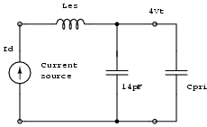
| The effective capacitance of the resonator as seen by the driver operating at the fundamental resonant mode. The inductance shown here is not the low frequency inductance of the coil, but is an effective value, valid only near the resonant mode, which is discussed later. |
We define the 14pF to be the equivalent shunt capacitance Ces of the coil when at (the fundamental) resonance. And 14pF + Cpri is the Ces of the resonator as a whole. The Ces is important because the following equations apply.
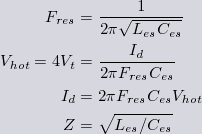
| Familiar equations for a lumped LC resonator. But the values of L and C employed here are not the 'low frequency' values, but are 'equivalent' values calculated to take account of the non-uniform distribution of current and voltage in the coil. |
Note that the large internal capacitance is apparently invisible to the driver and it may seem that the internal capacitance has been disposed of altogether, as it doesn't contribute at all to the external drive current or the effective shunt capacitance. But this is far from the case and we are only half way through the story. It turns out that, from the point of view of the driver, the internal capacitance manifests itself in the value of the effective inductance, Les. To understand this we have to digress now to discuss the inductance of the coil.
To begin a clear picture of the coil's inductance we must first
look at how the total induced voltage
is obtained in a coil from the induction in each turn.
Each of the N turns of the coil
has a self inductance, as well as a mutual inductance with every other
turn of the coil. With a current at low frequency passing through
the coil, and all the turns therefore carrying the same current, the total
induced voltage is proportional to the sum of the N self
inductance terms, plus the N * (N-1) mutual inductances.
The low frequency inductance of the coil as a whole is therefore the straight
sum of all the self and mutual components arising from the individual
turns (or whatever other unit of segmentation you care to break the
coil into). This defines the low frequency inductance Ldc,
which is the inductance obtained by all the various inductance formulae
such as Wheeler or Lundin.

| The low frequency inductance of the coil modelled in N segments is just the sum of all the mutual and self-inductance contributions. Here M(i,i) is the self inductance of the turn labelled i, and M(i, j) is the mutual inductance between turns i and j. |

| As the number of segments N is increased to an infinite number of infinitesimal segments, the discrete sum above turns into a continuous integral and M becomes a function of two continuous position variables. |
You must remember, the key feature of Ldc is that it only applies to the coil when all the turns carry the same current.
In this type of compact coil, all the turns are fairly
close to one another and therefore largely intercept the same magnetic field,
and consequently all have approximately the same induced voltage.
In other words, in a compact coil the self inductances of all the turns,
and all pairs of mutual inductances between turns, all have the same value.
This means that the elements of the matrix M of mutual and self
inductances of the turns are all the same value. Lets call this value
Lt - the self inductance of a turn. Then, for a compact coil
we have a simple relationship between the inductance of a turn and that
of the coil as a whole.

| For a compact coil where all the turns intercept pretty much the same magnetic field, all the self and mutual inductance coefficients are equal to the self inductance Lt of a turn. N-squared of these inductances all add to give Ldc. |
Remember, this only applies to a compact coil in which all the
turns are closely coupled to one another. In a
longer coil such as a solenoid, the mutual
coupling coefficients decay with the separation of remote turns
and thus the total inductance has to include a geometry factor,
called the Nagaoka coefficient, determined from the shape of the coil.
In our case, this coefficient is close to unity.
To find Lt for a compact coil, you can use, say, a Wheeler formula,
for the coil as a whole and divide the answer by N-squared. Or you can
apply a formula directly for the self inductance of a turn. You
can gauge the error in this 'compact' approximation by comparing the
two answers.
We will treat the flat spiral primary under discussion here as a 'compact'
coil. With the dimensions given, the total Ldc of the coil will
be about 19uH,
so that the each of the 4 turns, and
all 6 distinct pairs of mutual inductances all have the value
Lt = 1.2uH.
At high frequency the current, as we shall see, is no longer uniform and the
result is that the coil does not develop the same induced voltage (for a given
input current) as it did at low frequency.
In other words the apparent
inductance of the coil will be different from Ldc.
For the moment, pretend there is no internal capacitance at all, and
that only the external capacitance is present, plus perhaps a Cpri
at the 'hot' end of the coil.
Current into the first turn will equal the drive current Id.
Current into the second turn will be that of the first turn,
minus the current diverted into external capacitance by that point.
Likewise, after the next turn, a little more current has been shunted
to ground via external capacitance.
Describing the same thing from the viewpoint of the charges
themselves, some of the charge entering the coil gets 'hung up'
along the way in order to do the job of placing the coil's induced voltage
distribution across the external self capacitance.
The end result is the current leaving the coil into Cpri is less
than the current Id entering the coil from the driver.
In other words, the coil current is no longer uniform.
The significant consequence of this is that
the total induced voltage is less than would be obtained by an
inductance of Ldc, because turns further from the drive are not
carrying the full current and therefore not contributing quite as
much to the total induced voltage. This appears to the external
circuit as if the coil has an effective series inductance, Les,
somewhat less than Ldc.
In a regular secondary solenoid, the
reduction of inductance due to this might be 30% for an unloaded
coil and maybe only 5 or 10% for a toploaded coil. Observe that
the higher the load current is compared with the current diverted
into the distributed external capacitance, the more uniform will
be the coil current, and therefore the closer Les will
be to Ldc.
Well, that's the picture in the absence of any internal capacitance.
We reintroduce the internal capacitances and return to the 'frozen' view of
the circuit described earlier, in which
all currents are momentarily zero and the voltages across all
the capacitances are at their peak.
We can see that at this instant
the internal capacitances are all charged up
by the induced voltages across the turns of the coil which they span.
Now consider the fate of this 'internal' stored charge as the
resonator moves through the next quarter-cycle of oscillation.
At the end of this quarter-cycle, the H-field is now at a maximum and
the E-field has collapsed. In other words, the coil current is now at
a maximum and all the capacitances, internal and external and Cpri,
are completely discharged. Now we have already seen that the only charge
which the driver sees is that which passes through the external
capacitance. Therefore the internal capacitances will have discharged
through the turns of the coil, and as a result, will have increased
the total induced voltage over and above that which was being
produced when we only had the external capacitance. The 'hot' end
voltage is now higher, then, for the same input coil current Id,
than it was without the internal capacitance.
In other words, the effective inductance has been increased by putting
in the internal capacitances.
A very rough idea of the amount of extra induction can be obtained as
follows. Let the dominant inter-turn capacitance be Ct, in this case
780pF. For a turn-to-turn voltage of Vt, the charge across
each inter-winding capacitance is Qt = Ct * Vt
and this discharges into a turn with a peak current of
2pi * F * Ct * Vt
The original peak coil current, with just external
capacitance, would have been 2pi * F * Ces * 4Vt. Therefore,
the current has internally increased by a factor of roughly
1 + (Ct / 4Ces), which for our coil comes out to about a factor
of 15. The result is that the coil induces about 15 times the voltage
for a given input current than it would do without the internal current
caused by the turn-to-turn capacitance! Effectively the self inductance
has gone up by a factor of fifteen as far as the external circuit is concerned,
and the resonant frequency will be lowered by a factor of almost four.
We can broadly picture the internal capacitance
in terms of loops of currents 'circulating' within the coil itself,
passing through the turns as conduction current and closing their
loops via the displacement current of the internal capacitance. The overall
effect, as far as the outside world is concerned, is to increase
the effective inductance of the coil. One can think of the 'top'
voltage of the coil, ie that across Cpri, as induced through the
sum of the straight-through current (to Cpri) and shunt external C current,
(both of which the driver sees in Id),
plus a further voltage induced by the action of circulating currents
within the coil (which the driver does not see).
When we only had the external capacitance, the coil current was
highest at the input, equal to the drive current Id, and
everywhere else in the coil, the current was less. The Les
was therefore always less than the uniform current inductance Ldc.
But now that we have allowed the internal circulating currents to
come into play, the current within the coil will be larger (in places)
than the input current. In other words, the location of maximum current
has been shifted from the input of the coil to somewhere within the
coil. The effective inductance Les is now able to exceed
the low frequency inductance Ldc, and will do so if the
total contribution to induced voltage due to the internal loops exceeds
the reduction of induced voltage resulting from diversion of current
into external capacitance.
Thus we can expect to find that in some coils - those where internal
capacitance is significant - the
effective series inductance, Les, will
be larger than Ldc. In fact, this happens for solenoid coils of less
than about unity h/d ratio, and almost always occurs in flat spiral coils.
See TSSP: Equivalent Series Inductance for
a tabulation of the ratio Les/Ldc for a range of coil geometries.
In that table, flat spiral coils correspond to the row A = 0, and
solenoid coils correspond to the column B = 0. All the others
are conical coils of one shape or another. The compact ribbon coil
under discussion has A = 0 and a B value of around 0.1 or less, so
we can see from the table that Les is going to be more than
40% higher than Ldc purely due to its geometry,
and the presence of the large turn-to-turn
capacitance is only going to increase that percentage.
Remember that these ratios are all calculated for an unloaded coil. The
addition of a 'hot' end load such as Cpri will set up a straight
through uniform component to the coil current which will bring the value
of Les back down towards Ldc.
Incidentally, as the 'internal' contribution to Les is increased
by making the coil more compact, the location of the current maximum moves
towards the center of the coil, and the magnitude of the current max,
compared with the input current, increases. In extreme cases, virtually
all of the resonating current is 'internal' and hardly any of it is
looping out through the drive circuit, and the resulting
current distribution looks
more like that of a half-wave resonator - a small current at the ends
and a large current in the middle.
You can describe this in terms
of a coupling coefficient. With no internal capacitance, all of the
circulating current of the coil passes through the driver - the drive source
is coupled to the resonator with unity coefficient. As internal capacitance
takes effect, only part of the the coil's resonating current passes
through the driver and the coupling coefficient is less than unity.
There are two phases to modelling a coil. The first is to determine
the distributed reactances and represent these in terms of lumped
self and mutual reactances
between the segments into which the coil is decomposed.
The second phase is to model the resulting network of L, C and M
to determine the resonant frequencies, voltage and current distributions,
equivalent reactances Les and Ces, transfer (surge) impedances,
and so on.
The first phase - the determination
of the physical reactances, has already been done and the approximate
values were shown earlier in the equivalent network for the coil. We
will assume that Ldc is 19uH and that a 'compact' approximation is
valid so that all the L and M terms are equal to 1.2uH. We can now
construct a spice model, based on the earlier network but including all
6 pairs of mutual inductance by putting in a coupling coefficient of unity
between all pairs of the four turns.
Compact Spiral Primary - Test 1 .OPTIONS NOMOD NOPAGE CHGTOL=1e-16 .OP .AC LIN 10000 100K 20000K L1 N1 N2R 1.2e-6 R1 N2R N2 0.1 L2 N2 N3R 1.2e-6 R2 N3R N3 0.1 L3 N3 N4R 1.2e-6 R3 N4R N4 0.1 L4 N4 N5R 1.2e-6 R4 N5R N5 0.1 C1 N2 0 9.4e-12 C2 N3 0 2.2e-12 C3 N4 0 2.2e-12 C4 N5 0 9.4e-12 C5 N2 N3 780e-12 C6 N3 N4 780e-12 C7 N4 N5 780e-12 C8 N3 N5 4.8e-12 C9 N2 N4 4.8e-12 C10 N2 N5 4.7e-12 K12 L1 L2 1.0 K13 L1 L3 1.0 K14 L1 L4 1.0 K23 L2 L3 1.0 K24 L2 L4 1.0 K34 L3 L4 1.0 RL N5 0 1e12 IS N1 0 DC 0 AC 1 .PRINT AC V(N1) V(N5) .END |
An
ngspice
input file for this four-turn model. The four turns
are represented by L1 to L4 and in order to stabilise the circuit simulator
we have to put in a token small resistance for each turn, here 0.1 Ohms.
C1 to C4 are the external capacitances, C5 to C7 are the large inter-turn capacitances, and C8 to C10 are the smaller long-range mutual capacitances. The K are the mutual induction coefficients between each pair of turns. A small load resistance is added, again to satisfy the requirements of the circuit simulator. The current source is specified by IS and we ask the circuit simulator to calculate the input voltage V(N1) and the 'hot' end voltage V(N5) over a range of frequencies from 100kHz to 20MHz. For the time being, we have not included a primary tank capacitor. The current source is a token 1 Amp, so that when we plot the input voltage V(N1), we are also plotting the input impedance. |
This spice model is the basis for the following simulations.
We will model the coil both with and without the internal capacitance in order to demonstrate its effect.
| The drive current is a constant 1 amp. The model is run to determine the resonant frequency and the coil's output voltage Vhot. We then calculate the effective capacitance Ces = 1/(2pi * Fres * Vhot) and the effective inductance Les = Vhot/(2pi * Fres) |
The increase in effective inductance when the internal capacitance is
put in is dramatic - a factor of nearly 14 - which we were expecting from
our rough estimate earlier.
Note that Les without internal capacitance is somewhat lower than
the low frequency inductance Ldc of 19uH, also as expected.
The reader will hopefully appreciate by now the importance of attributing
the reduction of resonant frequency to an increase in effective inductance.
A more naive approach, which might have simply assumed that the internal
capacitance adds to the effective capacitance, would have seen a reduction
in frequency alright, but would have dramatically underestimated the
surge impedance
sqrt(Les/Ces) of the coil and so would seriously have underestimated the output
voltage as a consequence.
The above simulation was applied to the open-ended coil. We now add a primary capacitor to simulate a realistic primary tuning. For the sake of argument we will use a 3nF primary tank capacitor, and repeat the above set of simulations. The tank capacitor is represented by an additional statement CPRI N5 0 3e-9 in the spice model.
| The loaded coil has a much more uniform current, which pulls the effective inductance much closer to Ldc. Adding in the internal capacitance lowers the frequency further by raising the effective inductance, but not by much and the frequency prediction error if internal capacitance was left out would be only 2.5%. |
Now that the coil is loaded by a typical tank capacitor, the coil current is substantially uniform and the effective inductance is no longer raised by an extreme factor. We would not lose much accuracy if we left out internal capacitance between turns, nor in fact, would we lose much more accuracy if we left out the coil's self capacitance altogether, as is normally the case when primary coils are designed and modelled. With a tank capacitor of this size, even the extra large capacitance between consecutive turns of the ribbon conductor can probably be neglected.
The above are our definitions of the effective reactances.
We can make the following conclusions from this modelling exercise,
It is hoped that while estimating the effect of turn-to-turn capacitance in this unusual primary coil, we have shed a little light on the modelling process and clarified the often confusing concepts of distributed and equivalent lumped self-reactances. If you want to read more about the physics of resonant coils, visit the TSSP project's website. The self reactances of the coil are described in a little more detail (and a bit more math) in pn2511, and for the determined reader, the distributed resonance is described in terms of integral operators in a work-in-progress, pn1401.