It is essential that radio applications have accurate timing, so you will have a u-blox GPS module with USB interface and a PPS output. Connect up the GPS module to its antenna and connect the module to a USB port on the Pi. You should find a serial device ttyACM0 appears in the /dev directory,
ls -l /dev/ttyACM0
You can view the raw messages coming from the GPS with
stty -F /dev/ttyACM0 raw -echo
cat /dev/ttyACM0
If it's the first the time GPS module has been powered, it may take a while to find a satellite and download the ephemeris. Look out for the $GPGGA and $GPGLL messages which contain your latitude and longitude, and you'll see an incrementing time field in the GPGLL message.
Terminate the cat command with CNTL-C. Now install two essential packages, gpsd and ntp:
apt-get install -y gpsd ntp
ntp is the network time program and gpsd is a daemon which talks to the GPS. With the default installation, ntp does not talk to gpsd, and gpsd does not talk to the GPS! Some manual configuration is necessary to make the three components work together.
First, edit /etc/default/gpsd and change or set the following two options:
USBAUTO="true"
GPSD_OPTIONS="-n"
Then using your editor, create a new file /etc/systemd/system/gpsd.service containing the following:
[Unit]
Description=GPS (Global Positioning System) Daemon
Requires=gpsd.socket

[Service]
EnvironmentFile=-/etc/default/gpsd
EnvironmentFile=-/etc/sysconfig/gpsd
ExecStart=/usr/sbin/gpsd -N $GPSD_OPTIONS $DEVICES

[Install]
WantedBy=multi-user.target
Also=gpsd.socket
To set up the ntp daemon, edit /etc/ntp.conf and comment out or remove all the 'pool' statements. Add the following three lines
server 127.127.28.0 minpoll 4 maxpoll 4
fudge 127.127.28.0 time1 0.056 time2 0 flag1 1 refid GPS

restrict 192.168.2.0 mask 255.255.255.0
The 'server' entry tells ntpd how to find gpsd. The 'fudge' line tweaks some parameters of the GPS timing. The 'restrict' statement allows unrestricted access from your LAN. You must replace 192.168.2 with the first three numbers of the IP addresses used on your LAN, ie your class C network address.
Then, at the top of ntp.conf, add the line
tinker panic 0
This tinkering with the panic setting overcomes a problem caused by the lack of a battery-backed real time clock on the Pi. When it boots it starts up with the time remembered from when it was last on, which might be hours or days ago. ntp would normally refuse to step the clock by such a large amount and declare a fault. Actually, ntp would allow one large step but often when the Pi and GPS start up, it seems more than one large step is needed before it settles down to the correct time.
We might need to come back later to adjust the GPS time1 0.05 setting. This tells ntp how late the NMEA timing messages arrive after the UT second mark to which they belong. It accounts for processing delay in the GPS module itself, and for delay through the USB system. To adjust that requires monitoring the PPS from the GPS, which we haven't configured yet. So we'll set the fudge time1 parameter more accurately later and just use a ball-park 50mS delay for now.
Restart the Pi with
shutdown -r now
Log back in and run the command
ntpq -p
You should see something like
     remote           refid      st t when poll reach   delay   offset  jitter
==============================================================================
*SHM(0)          .GPS.            0 l    2   16    3    0.000   -0.401   0.926
The '*' indicates that ntp is using the GPS. If instead of a '*' you have a '+', it means that ntpd is talking to gpsd but gpsd doesn't yet have a proper fix on the time. Leave it a minute or two and try again. You can run the ntpq -p any time to check that the system time is working properly. The offset and jitter fields are in milliseconds.
You will also find that the ntp daemon is now making the time available to your LAN. Any PC on your LAN running an NTP client can now be set to use the Pi as a time source.
Now another useful but not essential package to install
apt-get install -y gpsd-clients
This installs a couple of utilities for monitoring the GPS. If your ssh client is on a X-Windows display, try
xgps
You'll need to run an xhost command on your workstation to give the Pi permission to connect to your display.
If you're not running X-Windows (you really should be), then use
cgps
for a text mode display of the GPS.
When gpsd is running, it claims the device node /dev/ttyACM0 so you can no longer directly view the NMEA messages as you did earlier with the cat command. But you can request gpsd to copy the messages to you, using a client program:
gpspipe -r
The -r option tells it we want the raw NMEA messages. You can monitor the functioning of the GPS with the gpsmon program:
gpsmon
This section describes the configuration of the Audioinjector stereo and Octo cards. These are the only viable sound capture devices for the Pi. USB sound dongles do not work properly on the Pi and probably never will.
Configuration is very simple, just edit /boot/config.txt to remove or comment out the line
dtparam=audio=on
and add one of the following two lines at the end. If you're using the stereo audioinjector, add the line
dtoverlay=audioinjector-wm8731-audio
or if you're using the Octo interface, add
dtoverlay=audioinjector-addons
Save and reboot. Check that the config has worked and the audioinjector is recognised by doing
cd /proc/asound
ls -l
and you should see the audioinjector listed, eg:
lrwxrwxrwx 1 root root 5 Feb 6 20:09 audioinjectorpi -> card0
and we can see that it is symbolically linked to card0. The built-in PWM output device on the Pi was disabled by commenting out dtparam=audio=on in the config file. This is because it would try to use the same I2S bus as the audioinjector uses.
Now that the audio card is configured, you need to install some software that can use it.
Start by installing a bunch of packages with the following apt-get commands:
apt-get install -y libasound2-dev libncurses5-dev libshout3-dev libflac-dev
apt-get install -y libsamplerate0-dev libfftw3-dev libpng12-dev libxpm-dev
apt-get install -y libx11-dev libforms2 libforms-dev
apt-get install -y sox gnuplot
Now download the latest version of vlfrx-tools from abelian.org:
cd /root
wget -nd http://abelian.org/vlfrx-tools/vlfrx-tools-0.9j.tgz
Unpack, configure, and install with:
tar xzf vlfrx-tools-0.9j.tgz
cd vlfrx-tools-0.9j
./configure --with-hardfloat
make install
You can test the installation with
cd test
./runall
It should finish after a few minutes with the message "All tests passed".
You now have a fully configured Raspberry Pi with a GPS clock, a very capable audio capture device, and a powerful suite of signal processing software.
You'll need to open three shells via ssh for this exercise. Some of the commands will be a bit different depending on whether you're running the stereo or the octo card.
Use the first of your shells to run the program vtcard to read signal from the audioinjector card. For the stereo card, use
vtcard -d hw:0,0 -b32 -r96000 -c2 -g-1 -v @raw
or for the octo use
vtcard -d hw:0,0 -b32 -r48000 -c8 -v @raw
The 'hw:0,0' tells vtcard to use device 0,0 (the first card on the system, the first sub-device) and 'hw' means to use a direct hardware interface. Note the use of -c8 with the Octo. Although there are only six inputs, the card supplies 8 channels from its CS42448 codec chip and vtcard has to be configured accordingly. The extra two channels are empty. The stereo card has a -g -1 option, this is because its inputs have reversed polarity: a positive input voltage gives a negative sample, and a gain of -1 corrects this.
vtcard will take a minute or two to begin work. It goes through a setup phase where it measures the sample rate against the system clock. You'll see a few 'setup' messages and then it will switch to printing 'run' messages. At that point, data becomes available in the output buffer @raw.
The 'run' messages are quite wide. You'll probably have to stretch the shell's window so that the lines don't wrap. You get a 'run' message every 10 seconds. The important fields are 'sr' which is the smoothed sample rate, and 'offs' which is the timing offset relative to the system clock.
Leave vtcard running in the first shell and use the second shell to monitor the signal in the buffer @raw:
vtstat @raw
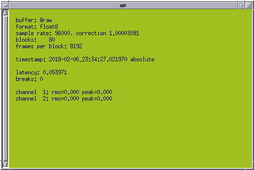
You'll see the timestamp of the stream and either 2 or 8 channels listed depending on your audioinjector. Something like the screen shot below.

All the channels should be showing rms=0.000 with no input to the card. On the stereo card, channel 1 is the left input, channel 2 is the right input. The 'correction' shown in the vtstat output is the factor by which the actual sample rate differs from the nominal sample rate of 96k/sec. Here, the actual sample rate is 96000 * 1.00003091 = 96002.96736 frames/sec. The timestamp should be counting upwards. If it freezes, it's because vtcard has noticed that the sample rate has drifted too fast for it to measure and it is resetting. It will resume after a minute or two. This shouldn't happen very often, especially once the Pi and audio interface are put into an enclosure.
It is necessary now to enable the line input and set the input gain. On the third shell, run
alsamixer
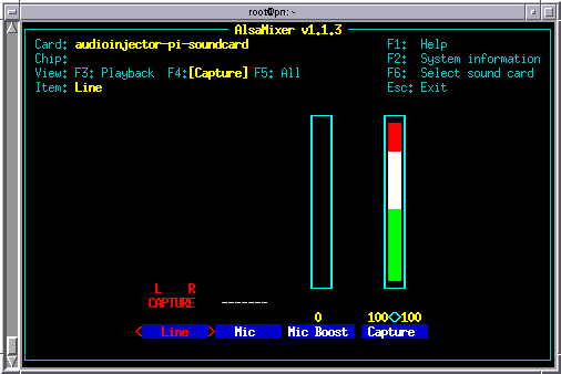
Press F4 to select capture controls and it should look like the screen shot below.

Use the left-right arrows to highlight Line input and press SPACE to activate it. Move right to the Capture control and the PgUp/PgDn keys can then be used to set the input gain. Set the input gain slider to its maximum. Your settings are automatically saved, and will be retained across a reboot. The stereo audioinjector has an analog input gain control potentiometer on the card itself. Always run with that control at full gain.
Now apply an input signal, perhaps from a VLF receiver or a signal generator, or some other convenient line level source. At full gain, full scale on the inputs is about 6.0V peak-to-peak, about 2.1V RMS. Don't worry if your source can't provide such a high level, the dynamic range of the card is sufficient to make good use of a smaller signal.
With some input applied, you should see some non-zero RMS and peak in the vtstat display.
If you're running X-Windows on your workstation, you can use vtscope to view the signal. Open another shell or use the vtstat shell to run
vtscope @raw
which will display 2 or 8 channels. To make it display just one channel, say, channel 1, use
vtscope @raw:1
or you can use a comma-separated list of channels, eg to display channels 1 and 3 on the Octo
vtscope @raw:1,3
This applies to all the vlfrx-tools commands where an input source is specified.
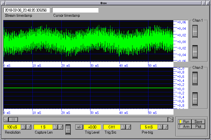
The screen shot below shows the vtscope window with a line level signal from an E-field connected to the left channel (channel 1). Typically there is a strong 50Hz component!

Experiment with the gain, resolution, and capture length controls. You can drag the mouse over the scope display to shift the trace and you can resize the scope display by picking up a corner with the mouse. Terminate vtscope with a CNTL-C in the shell.
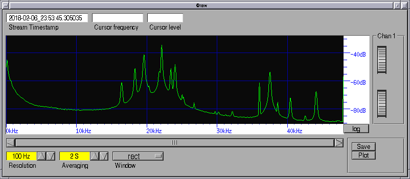
Look at the spectrum of the signal in @raw with
vtspec @raw
or perhaps
vtspec @raw:1
A screen shot of the vtspec window is shown below.

Now you have a working sound interface capturing signal into a lock-free buffer @raw which all manner of programs can then use. The signal is not yet timestamped by the PPS and is not yet filtered to remove mains and other interference. That's why I've called it @raw. Every system has an @raw and it provides the raw signal to input to various chains of signal processing.
You don't want to have to ssh in and start vtcard manually each time you use the system. Instead, we'll arrange vtcard (and later some other things) to start up automatically when you boot the system. There are various ways to do this. On recent Linux systems the easiest and most robust automatic startup involves making use of systemd - the program which is responsible for starting everything else up in the right order.
There is something of a class war going on right now with systemd. Many hate it because it doesn't conform to the usual standards and philosophy of unix programming. This is true, but the fact is, the old inittab and rc.d ways of starting things up and managing run-levels was getting stretched to its limits. Something like systemd was bound to emerge to replace it. Unfortunately the current systemd implementation is ugly, complicated and gives the appearance at least of being monolithic - none of which are normal attributes of unix programs. But it works and most Linux distributions use it now.
We start by inventing a system service, I'll call it 'radio'. Call it what you like. Create a file /etc/systemd/system/radio.service containing the following:
[Unit]
Description=Radio programs
ConditionFileIsExecutable=/root/radio
After=sound.target

[Service]
Type=forking
GuessMainPID=no
WorkingDirectory=/root
ExecStart=/root/radio start
ExecReload=/root/radio reload
ExecStop=/root/radio stop
User=root
Group=root
TimeoutStartSec=300

[Install]
WantedBy=multi-user.target
This file is placed under /etc/systemd/ so that it will not be affected by system upgrades. It tells systemd to either start, stop, or reload our radio programs by calling a script /root/radio. We just have to provide that script now.
Create a new file /root/radio with contents
#!/bin/bash

killall -q vtcard

if [ "$1" = start -o "$1" = restart ]
then

   sleep 2 # Delay needed when using Octo, the driver is slow to initialise

   vtcard -B -d hw:0,0 -b32 -r96000 -c2 -g-1 -L /run/vtcard.log -v @raw
   vtwait -t @raw
fi
That's for the stereo card, use -r48000 -c8 for the Octo card and leave out the -g-1 option. Note the -B option which tells vtcard to run in background, and -L which tells it where to write log messages to. The vtcard command is followed by a vtwait command. This waits until the @raw buffer is created and signal data is available. This is necessary because later we will add other commands into the /root/radio script, commands which depend on @raw existing, and we don't want to try to start them until @raw is ready for use.
Save and make it executable with
chmod +x /root/radio
That's how a text file becomes a 'script' in Linux: you use chmod to turn on the executable flag in its file permissions. Now enable the new radio service with the command:
systemctl daemon-reload
systemctl enable radio.service
The above enables the radio service to start automatically on boot. You can reboot now, or activate it directly from the command line with
systemctl start radio.service
The above command will take a minute or so to complete because it waits (the vtwait) until vtcard is in its 'run' state. That's why we put in a 300 second start-up timeout in the service file.
Now you can follow what vtcard is doing by tailing its log file:
tail -f /run/vtcard.log
Note that the log file is in a RAM filesystem /run here. This is to prevent vtcard from blocking when it writes log messages which can happen occasionally if the log is written to the SD card or some other disk, eg a USB external. If vtcard blocks too long, the sound card will overrun and the signal in @raw will stop for a minute or so while vtcard re-establishes its timing. This of course means that the log file will be lost on shutdown or reboot.
Now is a good time to demo a couple of useful utilities:
vttop
shows the CPU and memory usage of all the vlfrx-tools programs that are running.
vtps
lists all the vlfrx-tools processes and their command lines.
You can do quite a lot now with the signal in @raw, even though it is only roughly timestamped by the system clock. But you will not be able to do amateur radio things or combine or compare your signals with other receivers, until you have the signal timed by the PPS from the GPS.
Now is a good time to make a backup copy of the Pi filesystem, so that the work you've done so far wont be lost if something goes wrong. A backup just means making an image copy of the entire SD card. Shut down the Pi and move the SD card to a reader on your workstation.
On a Linux workstation, you would tail dmesg to determine the device node of the SD card, then use dd to copy
dd bs=4M if=/dev/sdX of=~/rp5-backup.img
On Windows you might be able to use Disk Imager, or the same program you used to copy Raspbian to the SD card.