Technical Details - Encoding and Transmission
Messages to be sent are restricted to a 6 bit character set consisting
of the upper case letters, digits, and a selection of space,
punctuation and other symbols. Lower case letters are mapped to upper case
before encoding. A total of 52 character codes are defined
which gives an information content of 5.7 bits per character. The table below
shows the translation of ASCII characters into 6-bit source codes.
Source encoding map
| ASCII source character | Source coded value |
|---|
| Decimal 42 (*) to 59 (;) | Codes 0 to 17 |
| Decimal 33 (!) | Code 18 |
| Decimal 61 (=) | Code 19 |
| Decimal 38 (&) | Code 20 |
| Decimal 63 (?) to 90 (Z) | Codes 21 to 48 |
| Decimal 10 (Newline, LF) | Code 49 |
| Decimal 9 (Tab) and 32 (Space) | Code 50 |
| Decimal 95 (Underscore) | Code 51 |
The 6 bit codes from the source encoding are
concatenated (lowest significant bit first) into a binary source block.
If the number of characters is NC, then the source block
length is NC * 6 bits and has information content
NC * 5.7 bits.
The outer error detection layer appends a 16 bit CRC to the source block.
The CRC is based on the CCITT standard with
polynomial hex 1021. A zero initial value is used in the CRC calculation so
that unmodulated carrier is a valid message.
The result is a message block of length NC * 6 + 16 bits.
The message block is encoded using a standard encoder which convolves the
block with one of the polynomial sets listed in the tables
here. For constraint length K the encoder
maintains K-1 memory bits.
The output bits are serialised
in the order in which the polynomials are listed in each set. The least
significant bit of each polynomial is combined with the current input bit and
the higher order bits combine with successively older memory bits.
After the last bit of the message block is encoded, the encoder memory
is flushed
with K-1 zero input bits.
This terminates the code and ensures that the final bits of the message block
benefit from the same error correction strength as the earlier bits.
The total number of output bits from the encoder is given by
(NC * 6 + 16 + K - 1)/R where R is the rate
of the convolutional code.
The total amount of information being encoded is NC * 5.7 bits.
Therefore the overall effective code rate is
R * (NC * 5.7)/(NC * 6 + 16 + K - 1)
The encoded block passes through an interleaver stage before transmission.
Encoded bits are loaded column-wise into a rectangular array, then read out
row-wise. If the size of the encoded block is NB bits, the
array has width given by W = ceil(sqrt(NB)) and height given
by H = ceil(NB/W). Any unpopulated array cells in a final
incomplete row are skipped during the readout.
The interleaved encoded block is transmitted by toggling the phase of the carrier.
Transmission begins at a precise time which is pre-arranged with recipients.
Technical Details - Reception and Decoding
VLF signals from the antennas are amplified, then digitised and timestamped
with reference to a pulse-per-second from a GPS. Up to three channels
may be received simultaneously, ideally from a pair of orthogonal magnetic
loops and a vertical electric field probe. All of the following processing
takes place in software.
The received signal is band limited to 3kHz width and passed through a
sferic blanker with threshold set to about 10 times the mean rectified
noise floor amplitude. With normal VLF conditions this results in
between 25% to 35% of the signal being blanked but the gain in signal/noise
ratio is around 20dB at 8kHz.
The sferic blanked signal is multiplied by a local oscillator at the
carrier frequency to produce a complex baseband signal. This is
further band limited and resampled to a sample rate of the order of
100 Hz. This is much wider than the signal bandwidth but the extra
spectrum is useful later for measuring the background noise.
The resulting stream of complex baseband timestamped samples are stored
to disk for later processing. The recording begins some 10 or 20 seconds
before the pre-arranged start time of the transmission. This allows the
sferic blanker time to establish a moving mean for its dynamic threshold
setting. The recording is stopped approximately one symbol period after
the expected end of the transmission.
The remainder of the signal processing is done by post-processing of the
recorded baseband signals.
The first step of post-processing is to mix the baseband signals to synthesise
a desirable antenna response. This involves correction for the known phase
and amplitude response of each channel, and for the effective orientation of the
loops. The antenna response is chosen to maximise the S/N ratio and the optimum
beam orientation may well be different to the great circle bearing in order
to steer away from the prevailing VLF background noise.
The received signal is invisible at this stage, so it is desirable to have
available some measurements of recent carrier transmissions as a guide.
The result of the antenna mixing is a single complex baseband signal. This
is coherently integrated per symbol period to produce an array of size
NB complex symbol amplitudes.
The complex symbol amplitudes are then
multiplied by a complex phase factor which is a guess of the signal phase
corresponding to a transmitted '1' bit. If the guess is successful,
all the signal will end up in the real channel. The quadrature channel
will contain only noise and is discarded to obtain the 3dB S/N gain of coherent
demodulation. An initial guess is obtained by summing the squared complex
symbol amplitudes which can extract a usable reference
phase from strong signals, and on weaker signals can bias the guess
in the right direction.
The interleaving applied by the encoder is reversed at this point.
The resulting array of NB de-interleaved real signal
amplitudes is
available to the Viterbi decoder. This employs a completely conventional
forward pass. The trellis is of size NB + 1 columns by
2^(K-1) rows and this dominates the memory required by the decoder.
The codes used are all of rate 1/n, therefore each node of the
trellis has two incoming branches and two outgoing branches. The branch
metric of each is calculated from the inner product of a vector of 1/R
consecutive input symbol amplitudes with a vector of 1/R expected symbol values with
amplitudes +1 or -1. This is equivalent to calculating the squared
Euclidean distance
in the code space. This soft decision detection gives a 3dB advantage over
the alternative of hard decisions based on a threshold of zero.
After the earlier sferic blanking and band limiting,
the noise is approximately Gaussian and therefore the inner product produces
log-likelihood branch metrics. The logarithmic branch metrics are
summed in the normal way to produce a pair of accumulated branch metrics at each
node of the trellis. The forward pass is easily parallelised to make
good use of multiple CPU cores.
The single backward pass of conventional Viterbi decoding is replaced by the
list
decoding algorithm due to Soong and Huang which is very well described
by Roeder and Hamzaoui in
this paper. The serial algorithm iteratively extracts backward
paths through the trellis in order of non-increasing path metric. The first
pass is exactly equivalent to the normal Viterbi backward pass. As the
backward pass proceeds, branches which diverge from the current best path
are placed into a sorted stack for later consideration. Subsequent backward
passes consult the top of the stack and examine paths which diverged from
a previously found best path. The backward passes cannot be parallelised
and can sometimes dominate the running time of the decoder.
The output from the list decoder is a series of decodes which each represent
a valid codeword of the convolutional code but with increasingly less
likelihood.
A typical list length considers up to 50,000 of the most likely decodes but
lists of up to several million can be effective.
Each decode of the list output is tested for a valid CRC applied by the outer
error detection code. Those that fail are discarded. This typically leaves
the correct decode in the list, along with sometimes one or two false
decodes which happen by chance to have a correct CRC.
The surviving decodes in the list output are then tested for valid source
encodings. Each character is represented by 6 bits, but only 52 of the
possible 64 codes are valid. If any of the 6 bit codes matches an
unassigned source code, the decode is discarded. By this simple scheme,
the spare
0.3 bits per character contribute to the strength of the outer code and allow
longer decode lists to be used, for greater overall performance.
If there are no surviving decodes, a new guess of the reference phase is
applied to the symbol amplitudes and the whole decode process is
repeated. Uniform phases are tried in either 30 degree or 15 degree steps,
moving gradually further away from the initial guess of the phase which was
derived from the signal.
Usually at VLF the decode is successful with a uniform reference phase.
If the full circle of reference phase has been tried, the message is split
into two parts and slightly different reference phases are applied to each.
Once all of these have been tried, the message is split into four pieces
and permutations of four different reference phases are tried.
The decoder finishes when all 108 variations of reference phase have been
tried.
When a successful decode is achieved, the trialing of reference phases
continues in the hope of obtaining a better decode (higher log-likelihood)
at some other nearby phase.
After each decode, some further processing is applied to measure the signal.
The decoded message is re-encoded and used to reverse
the original phase modulation. The result is an unmodulated carrier lasting
the duration of the whole message. This is coherently integrated over the
whole transmission to obtain an accurate measurement of average signal strength in
a very narrow bandwidth. The noise in the full bandwidth of the recorded
baseband signal is also measured to determine the noise spectral density,
and from this the carrier S/N and Eb/N0 are reported.
With a successful decode the received symbols are examined to count how
many of the symbols were demodulated incorrectly. From this symbol error rate
the S/N of the signal can be estimated. This usually agrees within a dB or
so with the average carrier S/N measured above.
From the carrier S/N, the actual value of Eb/N0 is calculated.
This calculation uses the information content NC * 5.7 bits, of the
message, and therefore is based on the overall effective code rate of the
cascaded codes, not the rate R of the inner convolutional code.
This Eb/N0 is reported along with the calculated
channel capacity.
Example
A message transmitted on 8822Hz by Dex McIntyre W4DEX in North Carolina
which was received and decoded in the UK provides a good example.
| Transmission
|
| Transmit ERP | Estimated 150uW |
| Message length | 25 characters |
| Symbol period | 8 seconds |
| Duration | 24320 seconds: 6 hrs, 45 mins, 20 seconds |
| Encoding | Rate 1/16 K=25 |
| Information content | 25 * 5.7 = 142.5 bits |
| Inner code block size | 25 * 6 + 16 = 166 bits |
| Encoder output | (25 * 6 + 16 + 25 - 1) * 16 = 3040 symbols |
| Overall code rate | 142.5 / 3040 = 1/21.33 |
| Bandwidth | 0.125 Hz |
| Reception
|
| Es/N0 (S/N in 0.125Hz) | -13.2 dB |
| Eb/N0 | -0.1 dB |
| S/N in 1Hz | -22.2dB |
| S/N in 2500 Hz | -56.2 dB, approx -76dB before sferic blanking |
| Symbol error rate | 0.38 |
| Rank in Viterbi list output | 89 |
| Viterbi list length | 50,000 |
| Channel capacity | 30.34 bits per hour |
| Capacity achieved | 21.1 bits per hour, 70% of capacity |
| Decoder memory | 49 Gbyte |
| Decoding PC | Xeon E5-2680 v2 32 core 2.8GHz 64 Gbyte RAM |
Decode time | 2.5 minutes |
The spectrogram on the right shows the signal from W4DEX after the decoder
has reversed the phase modulation to reconstruct the carrier. It is remarkable
that 140 bits of information can be reliably decoded from the signal. Without
removing the phase modulation, the signal is completely invisible in a
spectrogram beyond about 300km range.
The Eb/N0 of -0.1dB and the ranking 89th out of 50,000 in the decoder's output
list suggests that there was about 0.5dB or so of spare signal.
A slightly shorter symbol period would also have decoded and achieved a
higher channel capacity. The decoder still has a reasonable success rate
with Eb/N0 of -1dB but it is better to leave a bit in hand to allow for
phase variations. Several carrier transmission by W4DEX in the days
leading up to this test gave S/N variations of around +/-2 dB and the average
signal during the message was about in the center of that range.
Computers for Decoding
The Viterbi algorithm produces a true maximum likelihood decode of the signal,
is simple to implement,
and is very efficient for short constraint length codes. It works very
naturally with soft-decision BPSK and is easy to extend to list decoding.
The only problem with the Viterbi decoder
is that its memory requirements increase exponentially with increasing
constraint length. For this reason it is normally used only up to constraint lengths of 15 or
so. Its use up to constraint lengths of 25 is unusual because of the very large
amount of memory required for the trellis, of the order of 2 Gbyte per
message character. However, the latest generation of Intel based PCs
provide 32 or more CPU cores and up to 240 Gbytes of RAM which makes it possible
to experiment with long constraint lengths without having to use a less-than-optimum
serial decoding algorithm. Furthermore, such computers are readily available
to rent at low cost by the hour, typically less than 50 cents per hour for a
36 core 240 Gbyte machine. Considerable use has been made of this class of
machine via the
AWS EC2
service to develop and test the convolutional codes used by
this mode. It only takes a few minutes to start one or several
of these up and install
and run the decoder, and the whole process can be scripted.
A feature of convolutional codes is a diminishing return for increasing
constraint length. Dropping from constraint length 25 down to 21 for example
only incurs a fraction of a dB loss of coding gain. It takes hundreds of
hours of CPU time to actually measure accurately the difference in performance.
Consequently, not much is lost by using constraint length 21, or even lower.
This brings the decoder memory requirement within reach of domestic computers.
A machine with 4 GByte of spare RAM can handle a 12 character message with
constraint length 21 and a 30 character message with constraint length 19.
In any case, if PC developments continue at their recent pace - which they
will have to do to keep up with increasingly bloated web browsers and email
clients, it will
probably not be many years before the average home computer has 32 cores
and 64 GByte of RAM.
It is crucial for this mode of operation that the PC clocks at both ends
are synchronised accurately to universal time. The decoder relies
on the signal timestamps to know when each transmitted symbol begins
and it is desirable for the timing to be accurate to within 1/10th of a
symbol period.
Running the
ntpd daemon is sufficient
for symbol periods of 1 second and longer. If ntpd is able to use a GPS
directly connected to the receiver PC then even shorter symbol periods
may be usable.
The received signal should be timestamped at the point where it is
digitised, and at the same time the sample rate must be continuously
corrected for A/D conversion rate drift.
Spectrum Lab
for Windows and
vlfrx-tools for unix-like
systems will perform the GPS timestamping, sample rate drift correction,
and storage of signal to disk.
List Decoding Performance
The decode success rate of short block codes has an upper bound given by
the sphere packing limit. This refers to the probability that a received
noisy message will lie within the correct non-intersecting hamming sphere which
surrounds each valid code word in the code space. As the length of a code
block increases to infinity, the slope of the sphere packing limit steepens
and tends towards a vertical line at the Shannon limit of Eb/N0 = -1.59 dB.
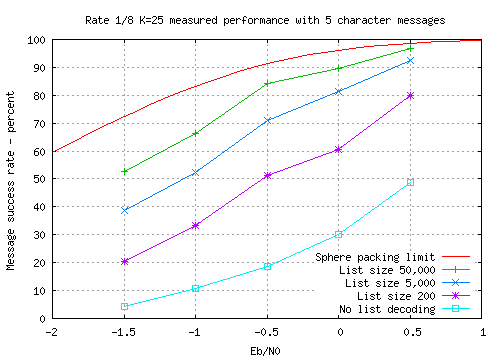
The sphere packing limit for the rate 1/8 K=25 code with 5 character
messages is plotted in the
graph along with measured performance points of the code. The limit is
calculated using the overall rate 1/19.65 of the cascaded combination of
inner convolutional code and outer error detection layer.
It is clear from the graph that list decoding increases the chance of
successful decode by a significant factor, in this case a factor of more
than 10
with the weakest signal. Without list decoding, a 50% success rate
is obtained at Eb/N0 = +0.5dB whereas a list size of 50,000 matches this
performance at Eb/N0 = -1.5dB. This represents an additional coding gain of 2dB
over and above the approximately 3dB coding gain of the K=25 convolutional
code at this message length and success rate.
The performance can be
brought closer to the limit by increasing the list length. As the sphere packing limit is
approached, the outer error detection layer begins to make errors in the form
of false detections as the capability of the CRC (and the redundant 0.3 bits
per character of the source coding) becomes exhausted.
This can be corrected by increasing the CRC size enough to
restore error-free operation. However, the resulting increase in overhead of
the outer
code produces a reduction of the overall code rate which in turn shifts the
sphere packing limit further away. Consequently the sphere packing limit
can be approached by longer and longer list lengths but it remains just out
of reach.
The number of bits used for error detection is nc * 0.3 + 16 where
nc is the number of characters. Therefore, for any given
list size, false detections are more likely when using short messages and each
additional three characters reduces the false detection rate by nearly 50%.
Although in principle the limit to list decoding is set by the error detecting
strength of the outer code, in practice the operator can provide a third layer
of error detection. In most cases a genuine decode will be immediately
recognised as a valid callsign, QRA locator, or greeting message. By
contrast a false decode caused by a chance match with the CRC will produce
a string of random characters which the operator will ignore.
Decoding Carrier
An unmodulated carrier is a valid message and decodes to a string of '*'
characters. This is useful for testing a path to see how short a symbol period
it will support. A long unmodulated carrier can be recorded and presented to
the decoder to test the decode performance using different code strengths,
message lengths and symbol periods - up to a maximum total duration limited
by the length of the carrier sample.
The cascaded code is linear,
therefore the performance of a carrier 'message'
is representative of any other message.
Output Files
After a successful decode, a data file is produced which gives
information about the received message. On the Windows version of the
decoder this file is named by replacing the .wav of the signal
filename with -symbols.csv.
If a better decode (greater overall log-likelihood) is found later in the
phase search, the file will be over-written.
The file has one row per symbol in the order in which the symbols were
received. Each row has comma separated fields as follows:
| Column | Contents |
|---|
| 1 | Symbol position, counting from zero |
| 2 | Symbol amplitude - in-phase component |
| 3 | Symbol amplitude - quadrature component |
| 4 | Symbol error: 1 if the symbol was demodulated incorrectly, otherwise 0 |
| 5 | The transmitted symbol, 1 or 0 |
It can be useful to plot column 4 (using impulses) against column 1 to see
if the symbol errors
were distributed uniformly, or whether parts of the message were received worse
than others. If the signal is strong, columns 2 and 3 can be plotted against
each other (using points)
to display a constellation diagram. However the $E_b/N_0$ needs to
be greater than +3 dB or so to see anything more than an amorphous central blob.
Most signals are much weaker than this (they should be, to make full use of
the channel capacity), therefore the constellation plot is rarely useful
except for local testing of your phase modulator and carrier stability.
Running Times
Some example decode times on an average quad core domestic PC.
The times given are for a full search through all
the reference phase patterns. If the message is going to decode, it usually
does so within about the first 10% of the full search time, during which
uniform phase patterns are tried. It may take more of a search if
propagation was disturbed or if one end of the link has oscillator problems.
| Code and message length | Run time |
|---|
| Rate 1/8 K=19, 31 characters, list 1000 | 9 minutes |
| Rate 1/8 K=19, 31 characters, list 50000 | 12 minutes |
| Rate 1/8 K=19, 31 characters, list 200000 | 16 minutes |
| Rate 1/8 K=21, 12 characters, list 50000 | 50 minutes |
The running time of the forward pass is proportional to message length and
also will double for each increment of K,
so K=21 will take four times longer than K=19. The backward pass running
time is roughly proportional to $N \log_2(N)$ where $N$ is the message length.
This can dominate when using low K and long lists with a long message.